The 0247-9 SAE J1939 Data Link Abnormal Update Rate fault indicates a communication issue on the J1939 CAN data link. The steps below outline how to troubleshoot and resolve the issue systematically.
Preparations:
Perkins EST 2024A & 2023A & 2019A Software Free Download
Perkins SPI2 2018A EPC+Service Manual Free Download
Perkins Communication Adapter 3
Overview of the J1939 Data Link
- The J1939 data link enables high-speed communication between devices.
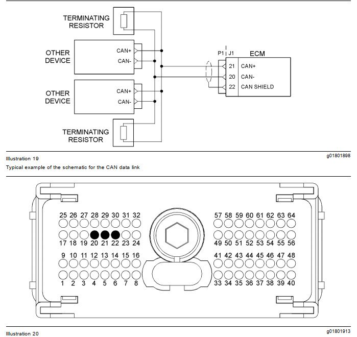
- Proper communication requires 60 ohms resistance between the CAN_H and CAN_L lines, achieved by two 120-ohm terminating resistors at each end of the network.
- The J1939 cabling is a shielded twisted pair, and any damage must be replaced with the same type of cable.
Step-by-Step Diagnostic Procedure
Test Step 1: Inspect Electrical Connections and Wiring
- Turn off the ignition switch.
- Inspect all connectors on the CAN data link circuit (e.g., P1/J1 connectors).
- Perform a 45 N (10 lb) pull test on all cables connected to the data link.
- Check the wiring harness from the ignition switch to the ECM for signs of:
- Corrosion
- Wear or damage
- Pinching or other physical defects
Expected Result:
All connections are fully seated, and the wiring is intact.
Outcome:
- OK: Proceed to Test Step 2.
- Not OK: Repair or replace the connector/wiring as needed. Clear diagnostic codes and verify resolution. STOP.
Test Step 2: Check the Terminating Resistor
- Disconnect the P1 connector from the ECM.
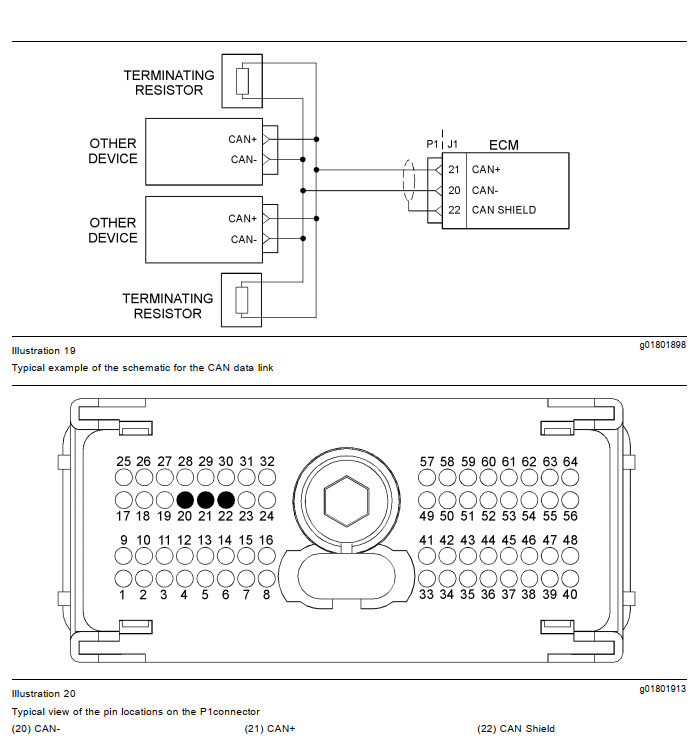
- Use a multimeter to measure resistance between P1:20 (CAN_H) and P1:21 (CAN_L).
Expected Result:
Resistance should be 50–70 ohms.
Outcome and Actions:
- 50–70 ohms (Result 1): The terminating resistance is correct. Proceed to Test Step 3.
- Less than 50 ohms (Result 2): Short circuit in the wiring harness. Repair or replace as needed, clear codes, and verify. STOP.
- 110–130 ohms (Result 3): One terminating resistor may be faulty.
- Locate and test both terminating resistors.
- Replace any resistor outside the 50–70 ohm range.
- If both resistors are good, proceed to Test Step 4.
- Greater than 150 ohms (Result 4): Open circuit in the wiring harness. Proceed to Test Step 3.
Test Step 3: Verify Data Link Cabling
- Disconnect any additional devices connected to the J1939 data link.
- Measure resistance between the following pairs of pins:
- P1:20 (CAN_H) and other CAN+ pins.
- P1:21 (CAN_L) and other CAN- pins.
- P1:22 (CAN Shield) and shield pins of other devices.
- Use a multimeter for these measurements.
Expected Result:
Resistance between all cables should be less than 2.0 ohms.
Outcome and Actions:
- OK: All resistances are within limits. Proceed to Test Step 4.
- Not OK: Repair or replace any faulty wiring or connectors, clear codes, and verify resolution. STOP.
Test Step 4: Check Other Devices on the J1939 Network
- Use an appropriate diagnostic tool to test all other devices on the J1939 data link.
Expected Result:
All devices on the data link function correctly.
Outcome and Actions:
- OK: Repeat the entire test sequence from Test Step 1 to confirm resolution. STOP.
- Not OK: Diagnose and repair faulty devices. Clear codes and verify resolution. STOP.
More trouble repair case for Perkins,pls refer to:Perkins Trouble Repair

