This guide outlines the steps to remove the fuel injection pump from a Perkins 800D series engine.
Related Contents:
Perkins EST 2024A & 2023A & 2019A Software Free Download
Perkins SPI2 2018A EPC+Service Manual Free Download
Perkins EST Interface EST Diagnostic Adapter 2024A With WIFI
Procedure
- Position Piston 1 at Top Center
Ensure that piston 1 is at the top center position on the compression stroke. Refer to the section “Locate the Top Center Position of Piston 1” in the “Operating, Testing, and Adjusting the System” manual for guidance. - Remove Screws and Plate
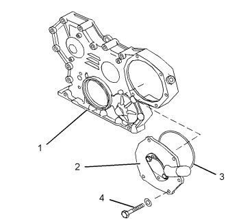
- Remove the two screws (4).
- Detach the plate (2) from the front housing (1).
- Remove the O-ring seal (3) from the plate (2).
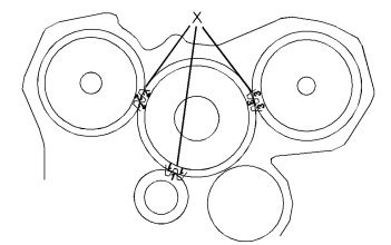
- Align Timing Marks
Verify that the timing marks (X) on the gear teeth are aligned. If not, create a temporary alignment mark on the gear to aid in reassembly. - Loosen and Remove Components
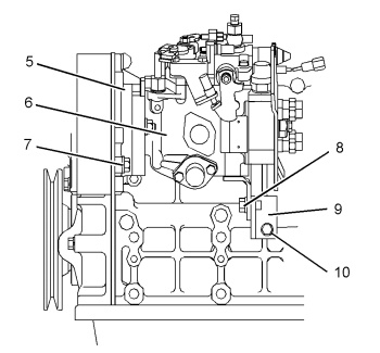
- Loosen the screws (7).
- Remove the fasteners (8), screws (10), and the bracket (9).
- Support and Detach Fuel Injection Pump
- Support the fuel injection pump (6).
- Remove the screws (7).
- Detach the housing (5) along with the fuel injection pump (6) assembly.
- Remove Guide and O-Ring
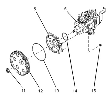
- Remove the guide (4).
- Detach the O-ring seal (13) from the housing (5).
- Loosen the Gear Nut
- Loosen the nut (11), but do not fully remove it.
- Detach the Gear
- Using tool (A), loosen the gear (12).
- Remove the nut (11) and the gear (12).
- Mark for Reinstallation (Optional)
- If reusing the original injection pump, mark the flange of the injection pump (6) and the housing (5) to ensure proper alignment during reinstallation.
- Remove Final Components
- Remove the nut (15).
- Detach the housing (5) from the fuel injection pump (6).
- Remove the O-ring seal (14) from the housing (5).
More trouble repair case for Perkins,pls refer to:Perkins Trouble Repair