The Scania 4-series lacks a coordinator and traditionally uses VCI1 to connect to the vehicle for running SD2/SP2 software. However, to read real-time engine data (e.g., with XCOM), you must connect to the CAN bus using VCI2. This requires a custom VCI cable and a software configuration to communicate with the Engine Control Unit (ECU).
Related Contents:
Scania SDP3 2.63.2 Truck Diagnostic Software
Scania VCI-3 VCI3 Heavy Duty Truck Scanner with software V2.53.5/V2.63.1
Requirements
- Hardware
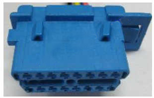
- Standard CAN connector (Scania P/N 1349719)
- Four cables (approximately 40 cm each)
- Two alligator clips
- Standard VCI connector
- Software
- XCOM diagnostic tool
Steps to Configure
- Build the Custom VCI Cable
- Connect the wires as follows:
- Pin 16 → Red alligator clip (power source)
- Pin 4 → Black alligator clip (ground)
- Pins 6 and 14 → CAN connector (for CAN High and CAN Low)
- Connect the wires as follows:
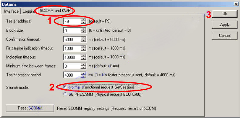
- Set XCOM Tester Address and Search Mode
- Open XCOM and navigate to the Options menu.
- Modify the following settings:
- Tester Address: Set to “F9.”
- Search Mode: Change to “S6 PRESAMM (Physical request ECU 0x00).”
- Confirm the warning message by selecting OK.
- Save changes and restart XCOM.

Note: These changes will configure XCOM (and compatible tools like SDP3, Gadget, CDev, and DMecNet) to exclusively scan for the EMS on the CAN bus. No other ECUs will be detected.
- Connect the VCI Setup to the Vehicle
- Attach the “homemade” VCI cable to the vehicle’s connection port located under the fuse box.
- Plug the VCI2 into the custom VCI cable.
- Start Diagnostics
- Launch XCOM. It should now be ready to connect to the ECU (EMS) via the CAN bus.
- Restore XCOM Settings
- Once diagnostics are complete, revert the changes made in Step 2:
- Reset the Tester Address back to “F9” (default) or the previously used address.
- Restore the Search Mode to its default setting.
- Save changes and restart XCOM.
- Once diagnostics are complete, revert the changes made in Step 2:

