The update for the JCB Backhoe Loader Power Sideshift wear pads provides detailed instructions on inspection, disassembly, and assembly procedures to ensure proper maintenance and extend the service life of the wear pads.
Inspection (Every 1000 Hours)
- Wear Limits: Replace wear pads when worn down to 6 mm (0.23 in) or less.
- Rotation: To extend wear pad life, you can rotate the upper wear pads 180° if their thickness is more than 6 mm (0.23 in).
- Grease Nipple: Replace the grease nipple when rotating the wear pads.
- JCB Heavy Duty Truck Diagnostic Tool JCB Electronic Service Tool with JCB ServiceMaster 4 V1.73.3 or V24.05
Disassembly Procedure
- Initial Setup:
- Park the machine on firm, level ground.
- Apply the parking brake and set the transmission to neutral.
- Lower the loader arms to the ground.
- Positioning:
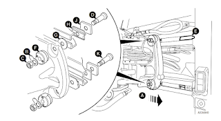
- Move the carriage to the end of stroke A (shown in center position for clarity).
- Lower the bucket to remove weight from the swingarm.
- Safety:
- Stop the engine, remove the ignition key, and operate the control lever to release any residual hydraulic pressure.
- Removing Components:
- Unlock the upper locking tab B and loosen nut C.
- Remove screw D from the slot in rail E.
- The hydraulic clamp F and washer G stay in place.
- Remove plate J and fit pad H.
Assembly Procedure
- Reassembly:
- Fit wear pad H, plate J, and screw D.
- Install a new locking tab B and mounting nut C.
- Adjust the hydraulic clamp distance as described in the “Sideshift – Adjusting the hydraulic clamp distance” section of the manual.
- Lower Clamp Adjustment:
- Repeat steps 5-11 for the lower clamp.
- Note: The lower clamp’s wear pad is on the opposite side of the rail from the upper clamp, so screw K does not need to be completely removed.
- If the wear pad is pinched, lower the bucket to relieve the load on the wear pad.
- Final Adjustments:
- Raise the bucket, position the carriage on the opposite side of the travel, and repeat the steps on the other side.
- After assembling all clamps, recheck the HydraClamp clearances on all clamps.
Software Reference
- Diagnostic Software: JCB Service Master 4 V24.05 Diagnostic Software 2024.05
This procedure ensures that the wear pads are maintained properly, extending their lifespan and ensuring optimal performance of the JCB Backhoe Loader Power Sideshift mechanism.